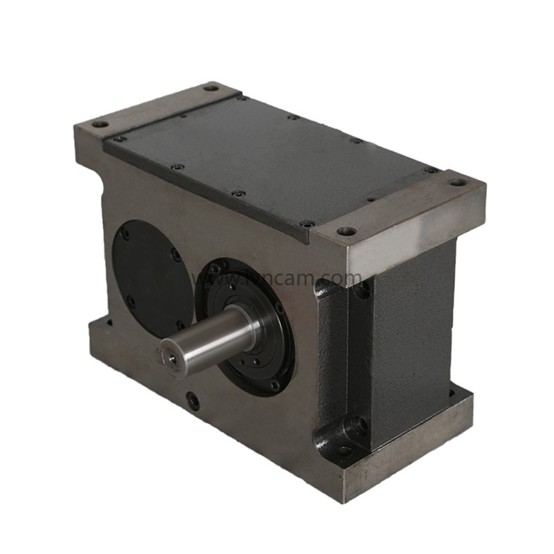
The structure of the cam divider is divided into two major systems: input drive system and output drive system.
In the mechanical transmission process of the divider, the structure and connection of the input drive system and the output drive system are crucial. The following are some common connection methods and precautions:
1. Input drive system connection:
The driving parts connected to the input shaft of the divider include pulleys, sprockets, synchronous pulleys, gears and couplings. Since the camshaft torque changes positively and negatively in one cycle, and the cam characteristics can only work at a certain speed, unstable rotation will apply additional torque to the divider and have an adverse effect on intermittent motion. Therefore, sliding belts, pulsating chains or gear drives with gaps should not be used on the camshaft. When using belts or chains, expansion operations are required. When using gears, high precision must be ensured and meshing gaps must be eliminated. The use of synchronous belts has many advantages, such as synchronization with other actions, no gaps, less vibration and high-speed transmission. In addition, the use of large-diameter pulleys can also provide a good flywheel effect.
Generally, the input shaft of the divider adopts a shaft input key connection structure. During the transmission process, due to the instability of various factors and the pulsation of the driving load, it is easy to cause the key connection to loosen and produce a matching gap. This will cause discontinuous movement of the input shaft and produce shock and vibration. Therefore, precise adjustment is required during the connection process, and the connection parts should be checked frequently during use.
2. Output drive system connection:
There are two output transmission modes for the splitter: direct transmission and indirect transmission. When choosing, try to avoid reverse impact.
The structures connected to the output of the splitter are as follows:
1. Connect the shafts by flange or sleeve.
2. The shaft and hole are connected by keys.
3. Connection between connecting flanges.
Since the output is intermittent, from static to moving and from moving to static, the inertia force is large. Coupled with the matching clearance of the connecting parts, it is often easy to cause looseness between the output end and the connecting parts. This will cause the output transmission parts to rush forward or lag and generate vibration. This will not only reduce the output accuracy, but also seriously damage the divider and the cam and needle bearings therein.
Here, it is important to note the following points:
1. The clearance between the hole and the shaft should not be too large, and the key connection should not be too loose.
2. Eccentricity or deflection is not allowed at the connection between the shaft or flange to ensure coaxiality.
3. When connecting the flange, nails should be added and bolts should be used for tightening.
Through reasonable selection and precise connection methods, the structure and connection of the input drive system and the output transmission system can be ensured to be firm and reliable, and the working accuracy and reliability of the divider can be improved.
related articles
- 2024 Dragon Boat Festival Holiday Notice
- LN125R roller cam CNC turntable servo turntable real shot
- 180DT-4-270R LVNCAM cam divider real shot
- I wish that spring will be peaceful and prosperous, and that people on earth and in heaven will be safe and sound.
- 2024 Qingming Festival Holiday Notice
- Shandong Luning Precision Machinery Co., Ltd. wishes everyone a happy Lantern Festival.
- 110DT-8-270R-T30 cam divider input shaft extension motor plate
- Spring Festival Holiday Notice-Shandong Luning Precision Machinery Co., Ltd.
- Why are cam dividers so popular in production?
- What should we pay attention to when cleaning and maintaining the cam divider?
- Domestic brand cam dividers: good quality, low price and can meet high requirements
- LN170-36-24S 170 four-axis CNC rotary table four parallel use case
- L80DT-8-LN003 Customer Selection Case
- L60DF-6-LN002 flange type cam divider six positions
- L140DT-6-LN001 Shandong Luning Platform Desktop Intermittent Cam Divider Six-station Large Hollow
